How to Create a Custom Replace Strategy to Prevent Overmilling on Conical Screw Channels
Overview
CAM software allows users to resolve toolpath calculation errors on unusual screw seat geometries by manually extracting the interface and assigning it a custom, known-working strategy. This is useful when standard algorithms calculate incorrectly, causing the tool to plunge too deeply and overmill the material.
Info: The default calculation algorithms sometimes fail on non-standard geometry. By bypassing these defaults and mapping the interface to a verified custom strategy, you can prevent workpiece collisions.
When to Use This Workflow
Use this workflow when you have a case where the generated toolpath is milling significantly deeper than the required depth for the screw stop. For example, this is helpful when working with a unique or unusual screw seat geometry that is similar to an existing library part but fails using standard automated replacements.
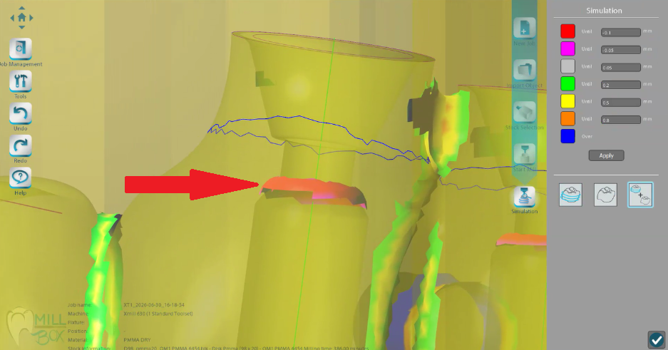
Figure 1: A red arrow indicates where default toolpaths overmill the material on unusual screw seat geometries.
This workflow helps you safely mill the restoration by forcing the software to use a specific, constrained toolpath strategy.
Important: This process is intended for advanced troubleshooting of problematic geometries. If standard replacement libraries are calculating the depth correctly, use the standard workflow instead.
Before You Start
Before using the manual extraction workflow, make sure you have identified a similar, properly functioning replacement currently in your library. You will need to reference this working interface to copy its underlying strategy code.
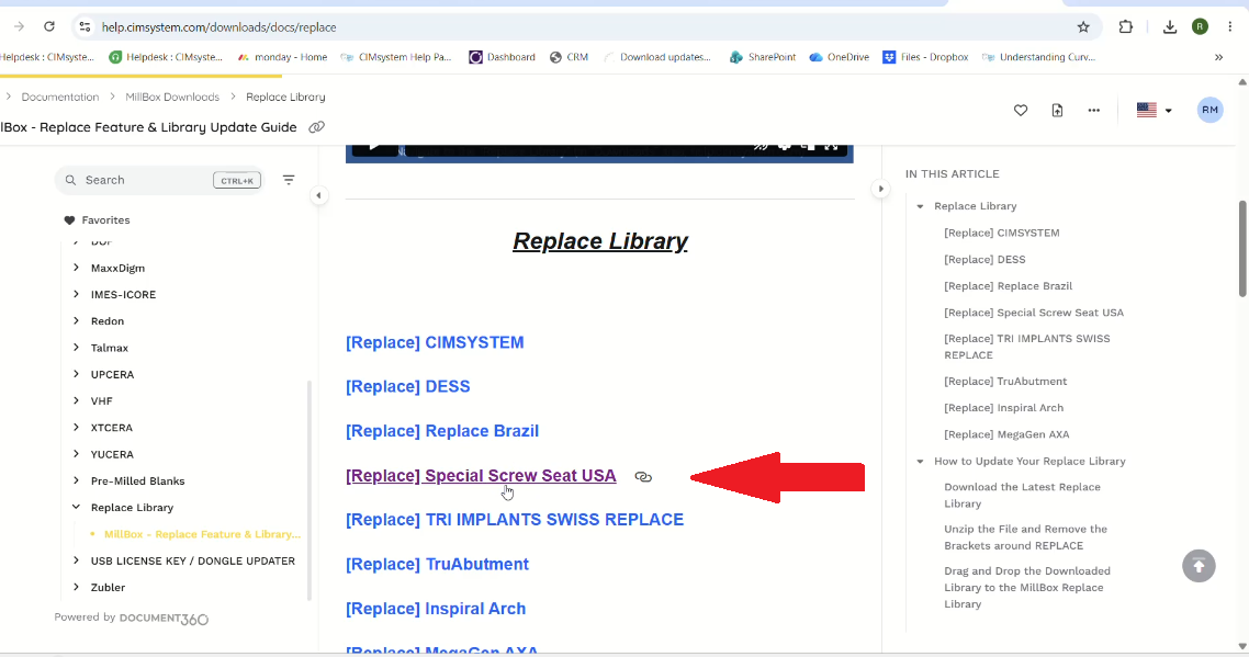
Figure 2: Locating a working replacement (e.g., "Special Screw Seat USA") online to use as a strategy reference.
You should also confirm that you have the necessary software permissions to extract and create library parts.
Note: Exporting connections and creating custom replacements typically requires an advanced or expert user license. If this feature is locked, reach out to us right away.
Step 1: Analyze the STL Interface
Examine the interface of the STL and visually compare it to the available models in your library. Note any geometric differences — such as missing lower cylinders or varying screw seat heights — to help identify the best match.
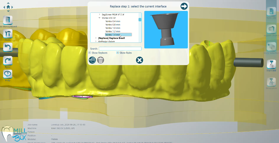
Figure 3: Selecting a similar, working interface to compare geometric differences against the target.
Tip: If you are modifying a similar existing interface to match your target, you may need to manually delete extra geometric elements (like a small bottom cylinder) from the 3D model to ensure the extracted result matches your target exactly.
Step 2: Export the Connection
Navigate to the top toolbar and go to Tools > Connection > Export. Select the interface on the 3D model that you wish to extract.
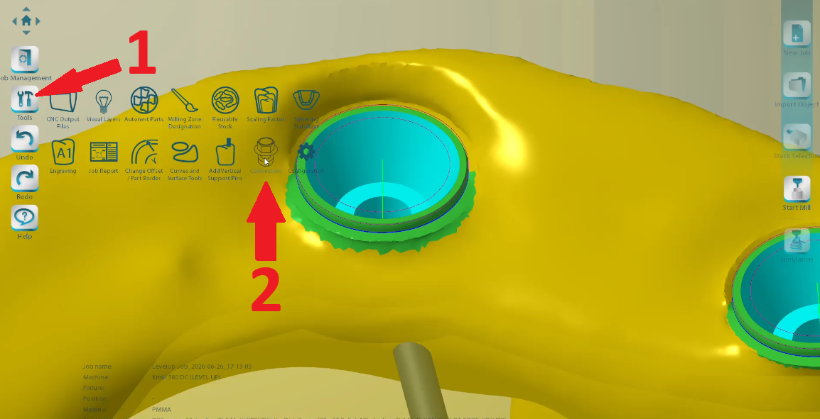
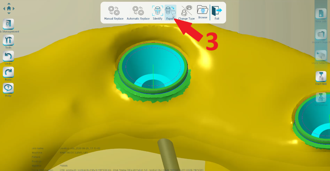
Figure 4: Navigating to Tools > Connection > Export to extract the target interface from the 3D model.
Step 3: Define the Extraction Volume
You must define a series of stacked cylinders to accurately capture the shape of the custom screw seat.
- Set the first cylinder to the required diameter and use a very small height (e.g., 0.01) to capture just the top boundary line without extending into the surrounding geometry.
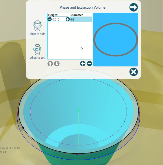
Figure 6: Using the "+" button to add stacked cylinders that mimic the internal conical shape.
- Click the + button to add subsequent cylinders, adjusting the height and diameter of each to mimic the internal conical shape of the screw seat.
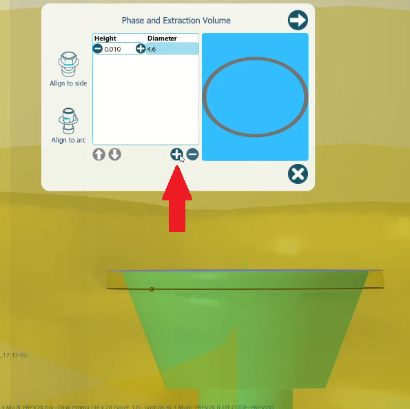
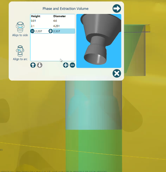
Figure 7: Shaping the cylinders to accurately capture the custom screw seat down to the flat bottom channel.
- Ensure the lowest cylinder captures a small portion of the flat channel at the bottom so the software properly identifies the base of the seat.
- Leave the alignment to the side unconfigured if dealing with a standard rotational interface, then proceed.
Important: When extracting the volume using stacked cylinders, it is absolutely crucial to capture a small portion of the flat channel at the bottom. If this flat base is not properly identified, the software will not know where the toolpath should stop, and the overmilling issue will persist.
Step 4: Configure Replace Parameters
In the parameters window, select the appropriate destination library from the root list for your region or implant type. Input a distinct, recognizable name for this new custom replacement in the replace name field. Finally, check the box labeled Custom strategy.
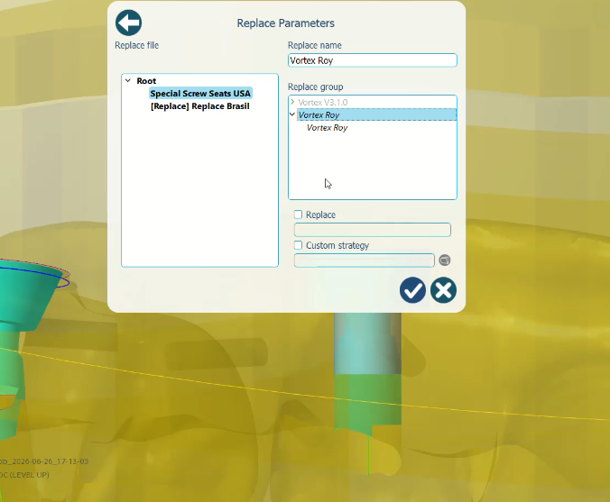
Figure 8: Assigning a distinct name (e.g., "Vortex Roy") to the new custom replacement.
Step 5: Identify the Correct Custom Strategy Code
To ensure the toolpath generates correctly, you must assign the same underlying strategy code used by the similar, successful interface you identified earlier.
- Open your computer's file explorer and navigate to your CAM software's library directory.
- Locate and open the primary configuration text file (often named replace.txt).
- Scroll through the document to find the entry for the known-working interface.
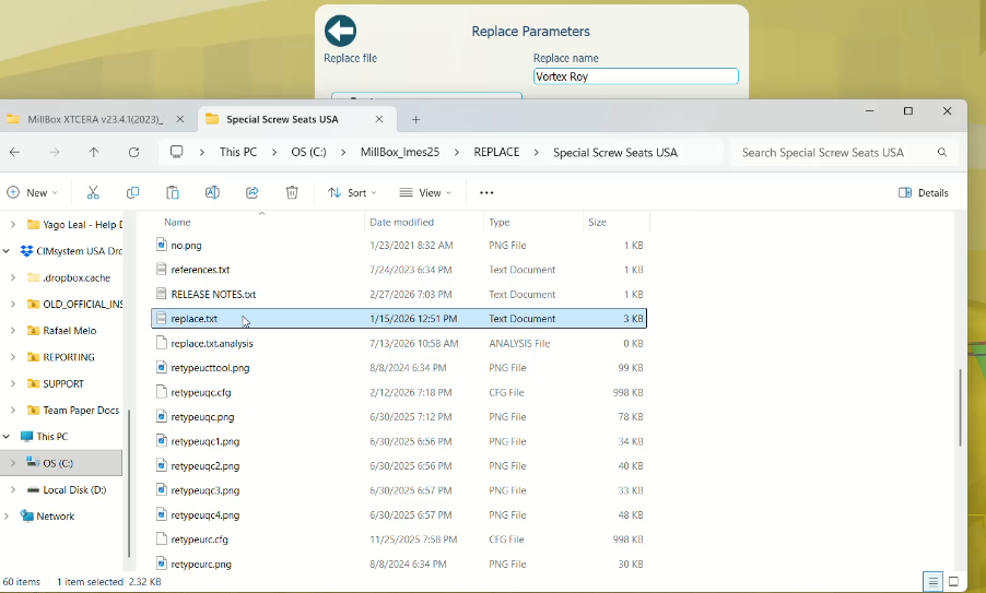

Figure 9: Finding the underlying strategy code (e.g., "retypeusc") in the replace.txt configuration file.
- Identify and copy the specific custom strategy code associated with it.
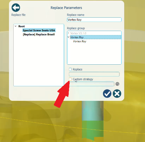
Figure 10: Checking the "Custom strategy" box to allow assigning the copied code.
Step 6: Apply the Strategy and Finalize
Return to the CAM software and look at the Custom Strategy selection window. Locate and select the matching strategy code you found in the text document. Click the checkmark to confirm.
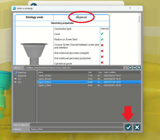
Figure 11: Selecting the matched strategy code ("retypeusc") and clicking the checkmark to confirm.
Info: MillBox will prompt you to apply the extracted interface to the current connection. Select Yes or No as needed. The custom interface is now permanently saved to your library.
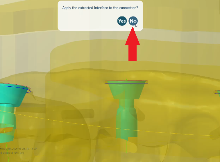
Figure 12: Selecting "Yes" or “No” to apply the extracted interface to the current selected connection.
Step 7: Apply the New Replace
Go to the Manual Replace function in your top toolbar and select the target connection on your restoration. Your newly created custom interface will now be available in the library list. Select and apply it to the connection.
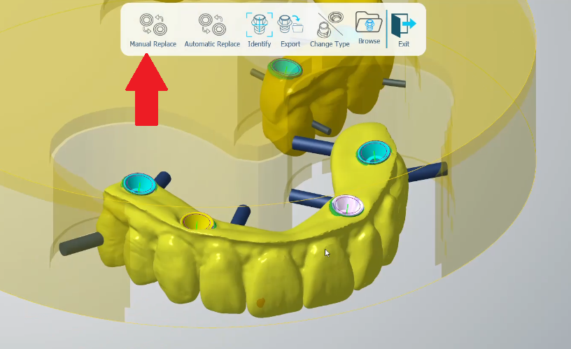
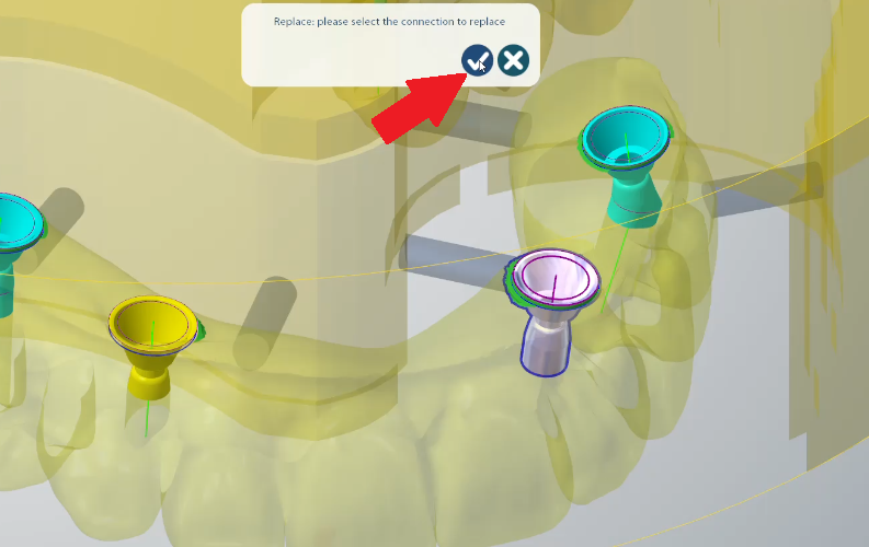
Figure 13: Clicking the "Manual Replace" tool to begin applying the new interface and confirming the specific target connection on the 3D model by clicking on the check mark.
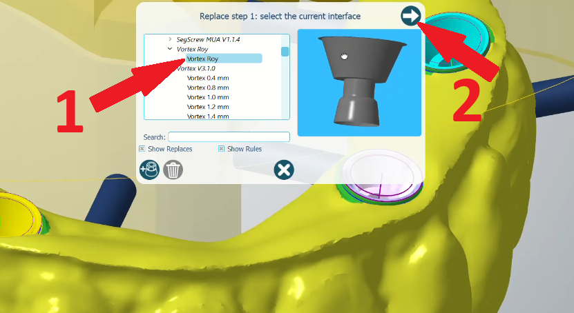
Figure 14: Selecting the newly created custom replace from the library list to finalize the application.
Best Practices
- Use clear and distinct names for your custom replacements. This is especially important when sharing databases across multiple workstations so other technicians know exactly what the custom replace is intended for.
- Always do a visual check of the simulated toolpath after calculating to verify the custom strategy successfully stopped the overmilling.
Tip: Keep a log or document of the custom strategy codes you frequently use for your specific implant systems to speed up this process in the future.
Troubleshooting
If the export connection tool is grayed out: Confirm that your software dongle or license has the advanced module active. If it does not, you will not be able to extract the interface.
If the toolpath still overmills after applying the custom replace: The extraction volume may not have captured the bottom of the screw seat correctly, or the assigned strategy code does not contain the proper depth constraints. Re-extract the interface, paying close attention to the final cylinder in Step 3, and verify the strategy code in Step 5.
Note: If performance or calculation issues continue, try deleting the calculation files for that specific part and running the calculation from scratch with the new replace applied.
Final Review
Before calculating the job and sending the file to the mill, confirm the following:
- The target interface was accurately captured using the extraction cylinders.
- The custom strategy box was checked during setup.
- The correct strategy code from a verified, working interface was applied.
- The new custom replace was manually applied to the correct connection on the restoration.
- The visual simulation confirms the toolpath no longer plunges past the required depth.
Important: Always verify the toolpath simulation visually before sending anything to the machine to guarantee that workpiece collisions have been fully resolved.
Need Assistance?
If you need help confirming your software build supports interface extraction, validating your extraction volumes, or troubleshooting specific strategy codes, the Level UP CAD/CAM Support Team can assist.
You can submit a support ticket through the support portal or contact us directly at support@levelupcadcam.com.